

Replace your Original Door lock

With a Modern RV Lock

Thank you for purchasing the Camping Treasures Door Lock replacement kit.
Our kit is designed so the average person can replace the original “L” handle “slam latch” used on 1968 to 1974 boler trailers with a modern Bauer lockset.
NOTE: Read these instructions thoroughly before you start your installation.
Great care was taken in designing our kit so it would fit most trailer doors, but some modifications to the door or spacer plates may be required for some applications.
Use the following instructions as a general guideline. Ideally your current door thickness should be between 1⅛” to 1⅜” thick.
If you have any questions, tricks or tips please contact me
Although these instructions may appear to be long, I have tried to make them as comprehensive as possible to help you install your new door lock.
Please read and understand the full written instructions on the Camping Treasures website before starting to install your lock replacement kit
NOTE: Some pictures, although they accurately represent the installation of the door lock, are from the installation on a newer boler. I will update pictures as soon as I can.

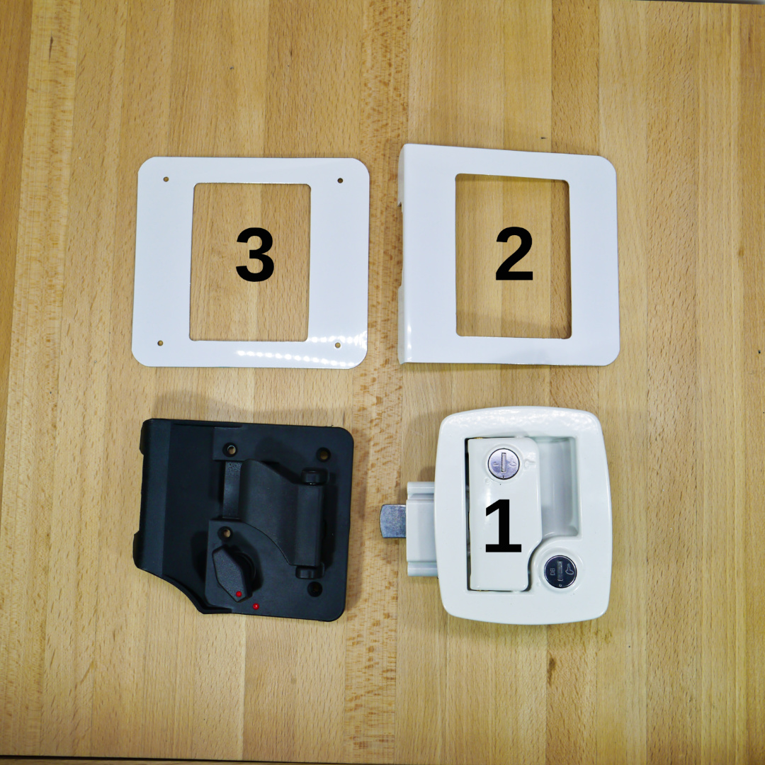
We have included all the parts and hardware needed for a typical installation
- Bauer Door lock, packaged (White or Chrome)
- Inner aluminum adapter plate
- Outer aluminum adapter plate
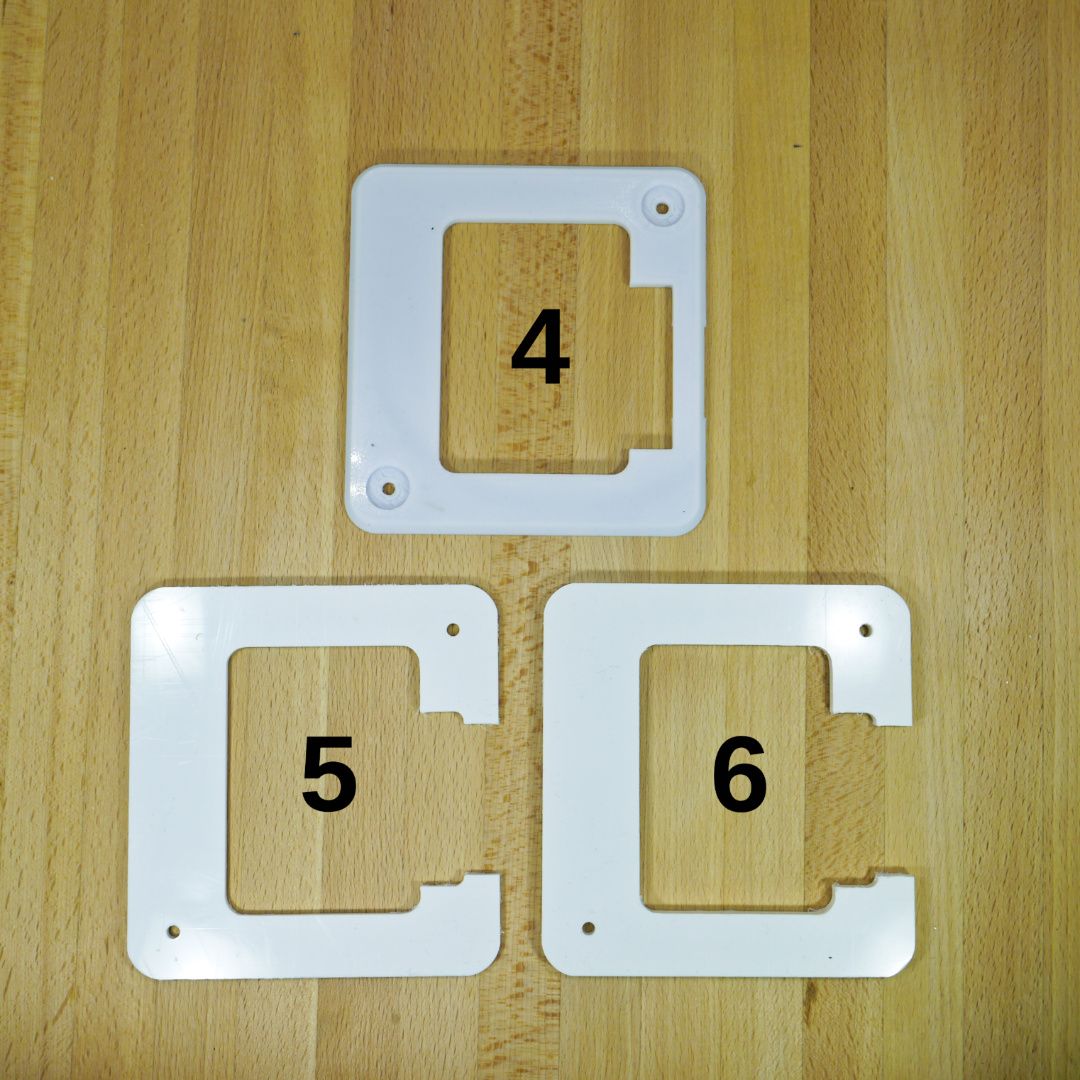
- ¼” Latch cover
- ⅛” Spacer (only used if needed based on door thickness)
- ¼” Spacer (only used if needed based on door thickness)
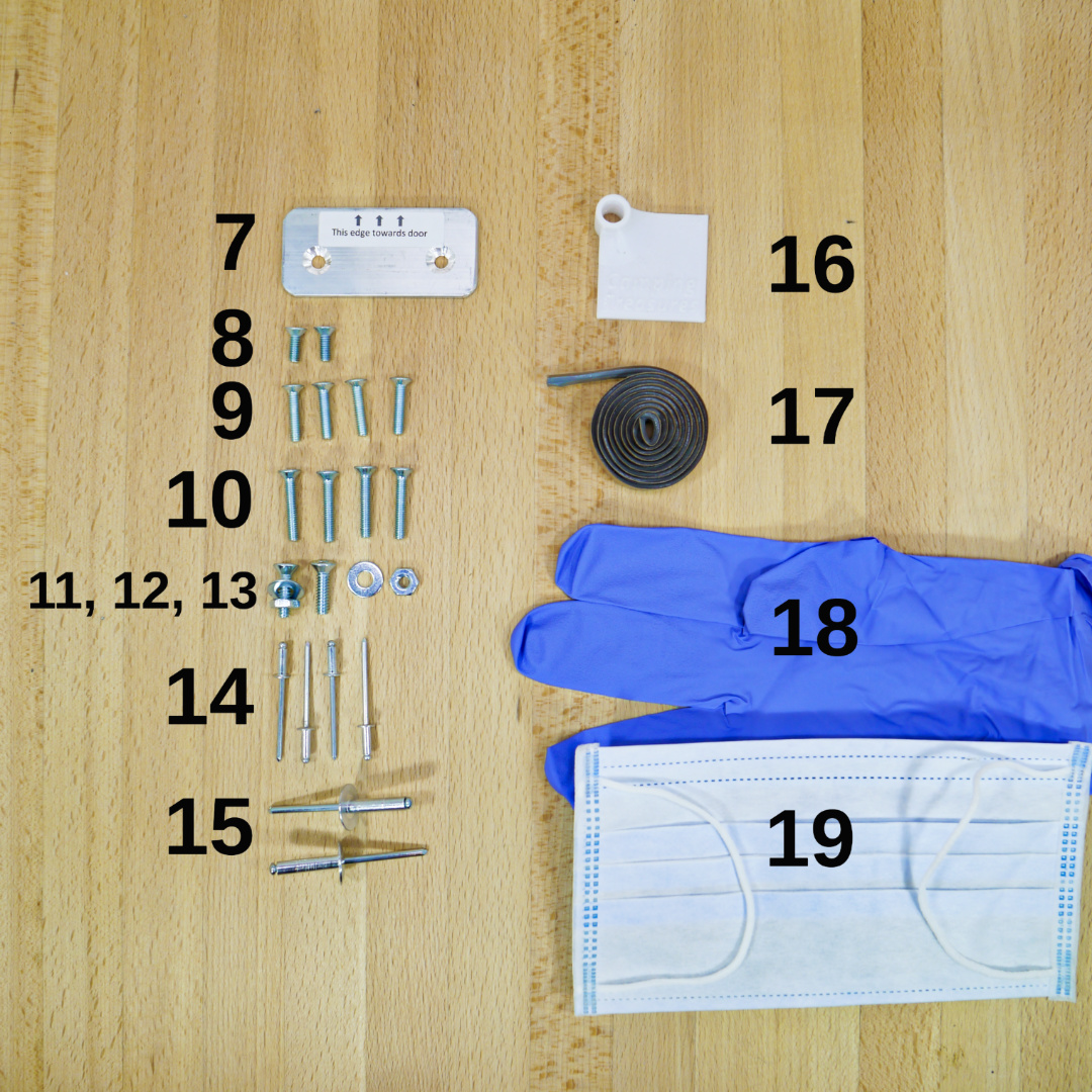
- Aluminum Striker Plate
- 2 – #8-32x½” Pan Head Machine Screws (secure end of door latch in door edge)
- 4 – #8-32x¾” Pan Head Machine Screws (attach inner lock handle to door lock)
- 4 – #8-32×1” Pan Head Machine Screws (Optional door handle screws, may be needed if door slightly thicker)
- 2 – #10-24x¾” Flat Head Machine Screws (11, 12, 13 attach striker plate)
- 2 – #10 Flat Washers
- 2 – #10-24 Nuts
- 4 – ⅛” Aluminum Rivets (attach outer aluminum adapter plate)
- 2- 3/16″ large head rivets (attach latch cover and requires spacers to door)
- Drill guide
- Butyl Sealing Tape
- Disposable Gloves
- Dust Mask
NOTE: Due to the global supply shortage, the dust mask and disposable gloves identified in the instructions we will not be included in our kits until further notice
*2 additional striker plates are included that are usually not used for installing this kit in a Boler but may be needed if using this kit on another application, extra parts are included with the lock in a separate package
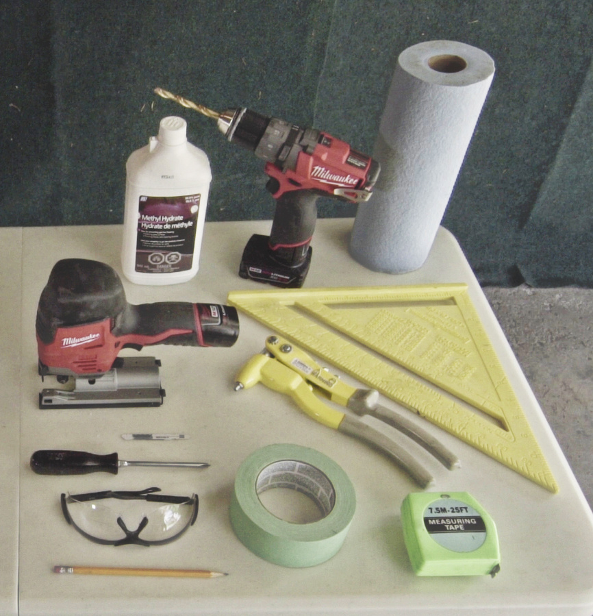
You will need to supply an assortment of tools and some supplies
- Die grinder or Dremel (or similar) with small cutoff wheel (a hand saw with a very fine blade may also be used)
- Masking or Painters tape
- Pencil or fine marker
- Screwdriver, Phillips, Robertson (square) and Slot
- Safety glasses
- Paper towels or rags
- Petroleum free solvent such as; Methyl Hydrate or Methyl Alcohol, Acetone, Mineral Spirits, Brake Cleaner
- Pencil or fine marker
- Drill with 1/8”, 3/16″ and 5/16” drill bits
- Jigsaw with fine metal cutting blade, or similar hand saw
- Tape measure
- T-square
- File
- Pop rivet gun
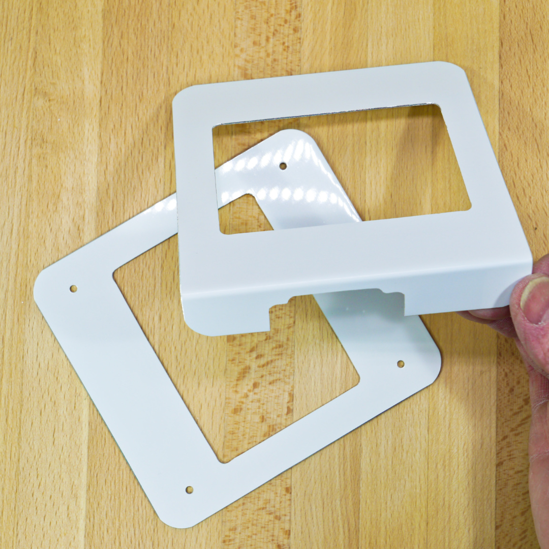
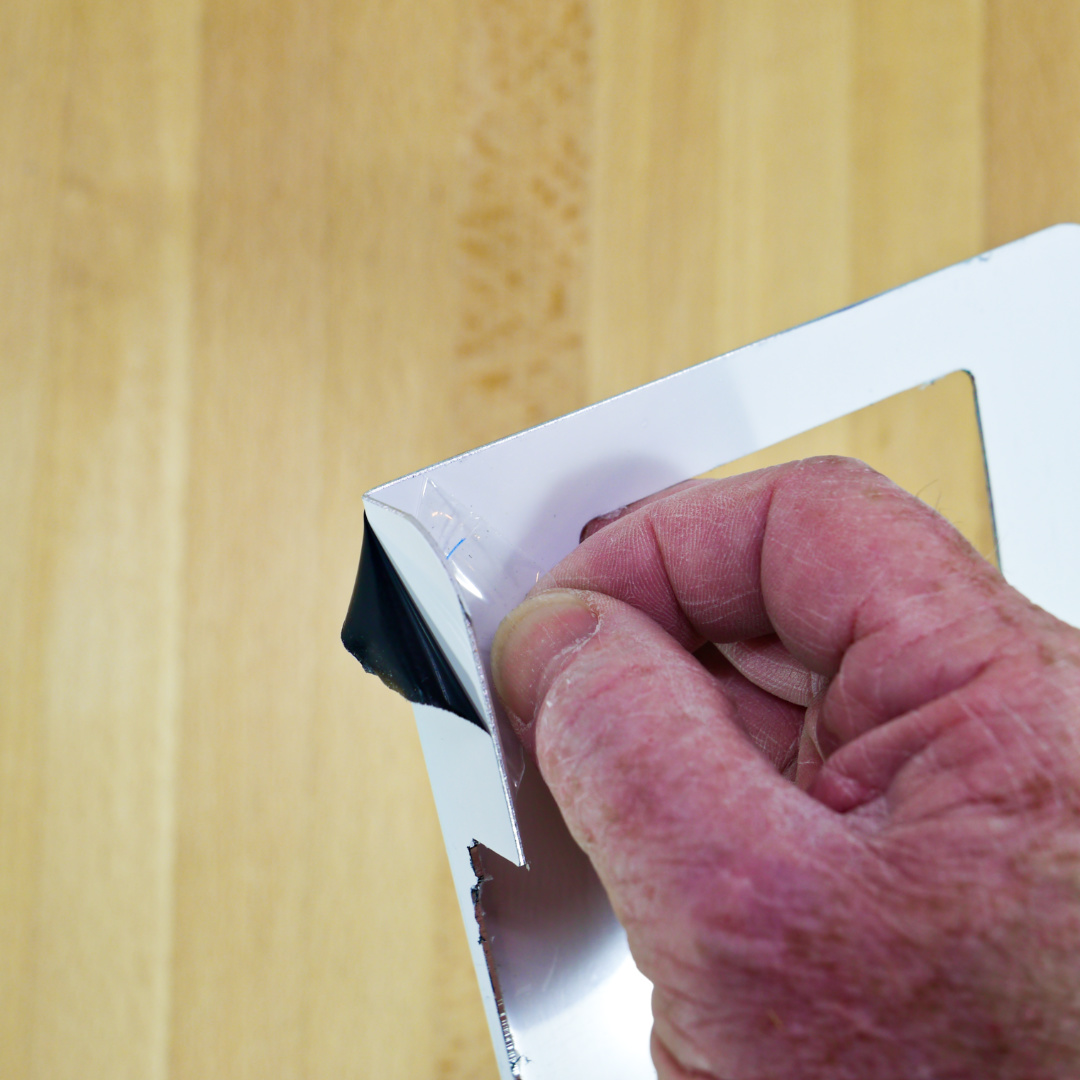
The Aluminum Adapter Plates in our kit are supplied with a durable white factory painted finish. A protective film is applied to both surfaces and should be removed before final assembly
The white factory finish is very durable that will last many years, you can paint over this finish to match the colour of your trailer, lightly sand the surface before following the manufacturer’s instructions on using the paint of your choice.
To Paint:
- Sand the surface lightly with 320 grit or finer sandpaper
- Prime and Paint with a quality paint.
Preparation
Removing the Original Lock
Although you can replace the lock with the door installed on the trailer it is much easier to work on the door with it removed.
To remove the door remove the bolts running vertically through the hinges. Here are instructions and video, this would be the ideal time to check the condition of the hinge parts and replace them if they are worn. https://www.campingtreasures.com/instructions/rebuilding-boler-scamp-hinges/
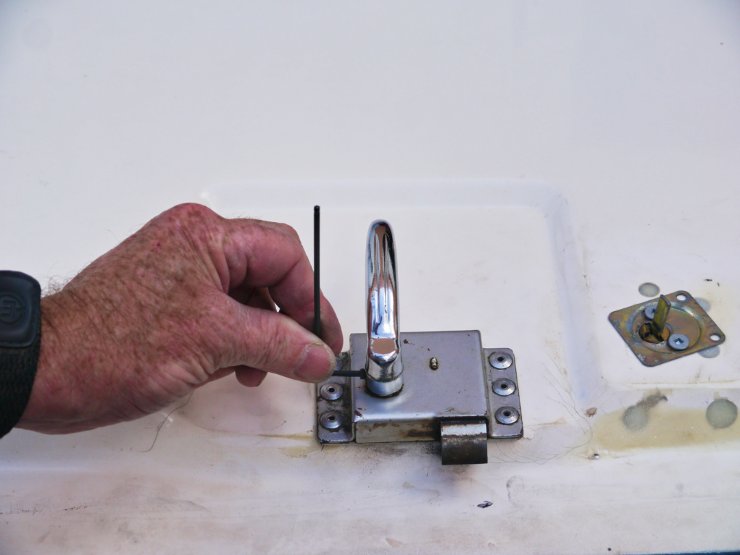
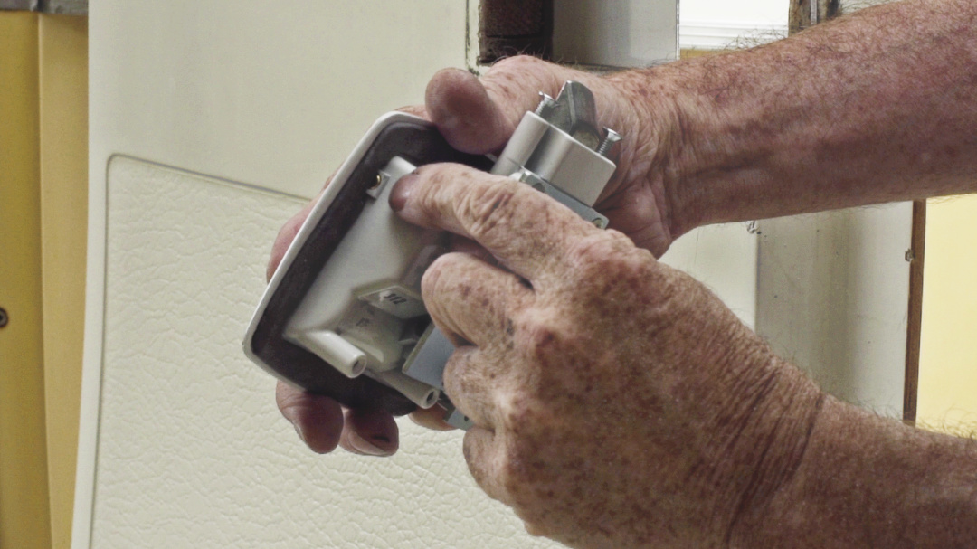
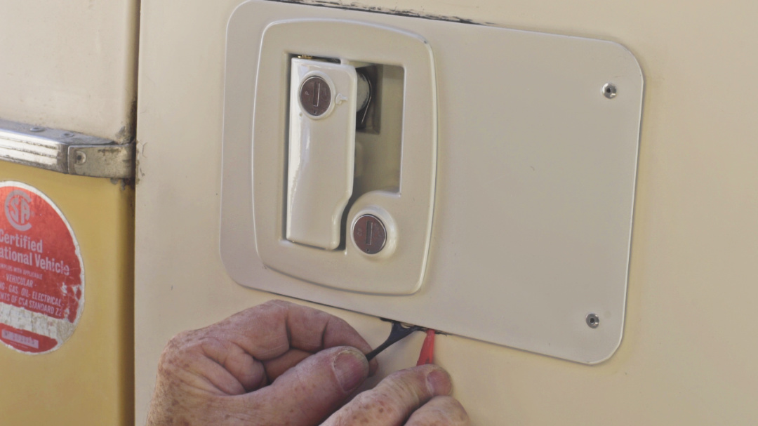
Remove Inner & Outer Handle
- The inner door handle is usually held on with a small set screw, using a small flat blade screwdriver, or in some applications a small allen hex key, loosen the handle and pull it straight off.
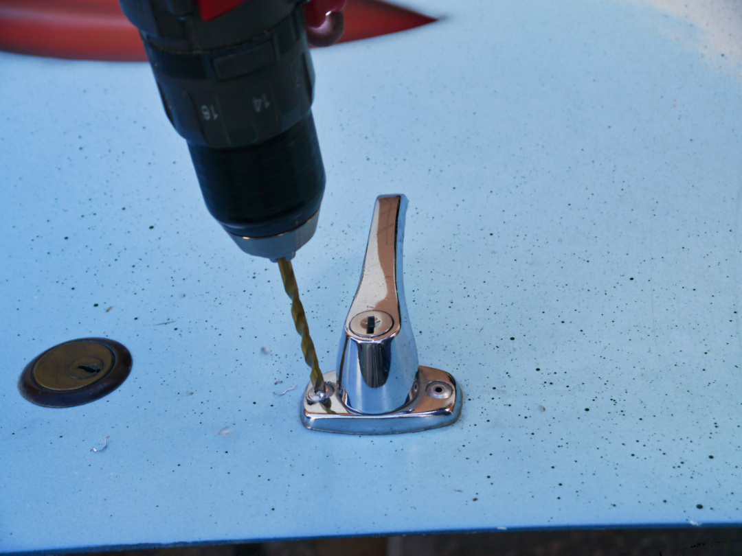
- The outer handle is usually held on with 2 large rivets, drill out these rivites being careful not to damage the door. With the handle loose it should pull straight out, In some cases you may need to apply some penetrating oil to the lock where the square shaft goes through it on the inside of the door. Gently tap on the end of the shaft inside the door until the outside handle and shaft are free and pull straight out to remove.
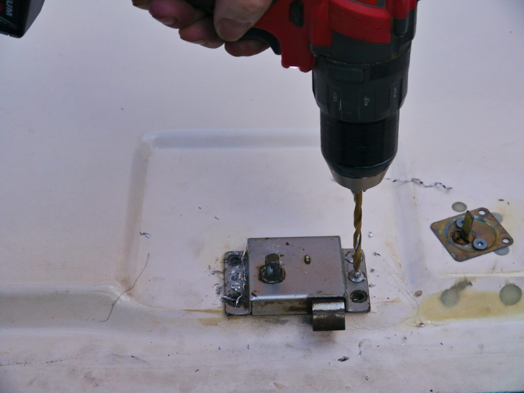
Drill out the rivets
Carefully drill out the 6 rivets that hold the lock to the door, remove the lock and drill, file or grind any remains of the rivets in the door flush and smooth
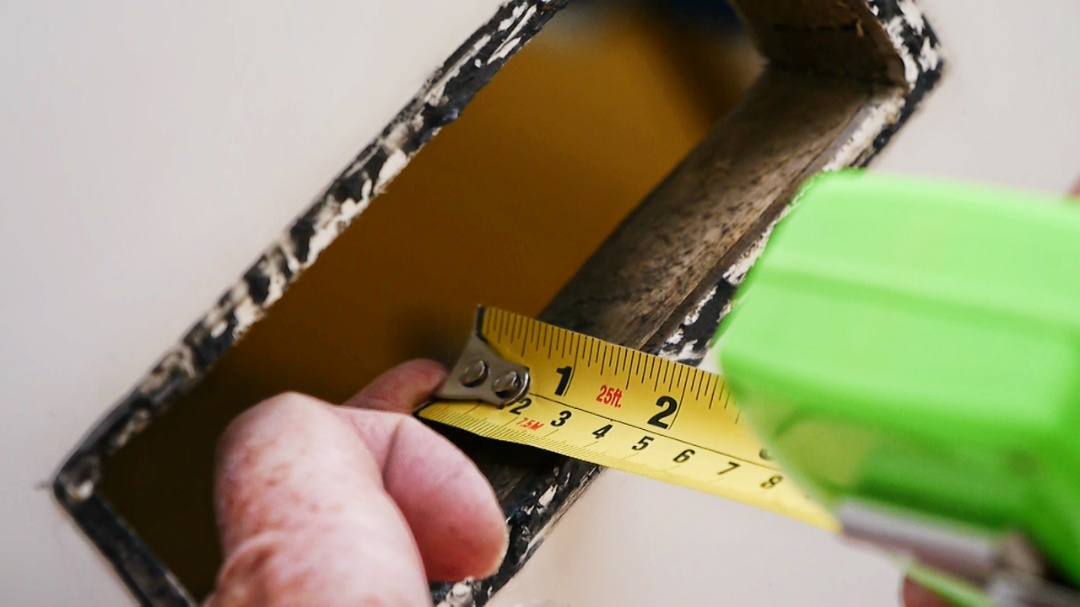
Measure the Door
- With the lock removed measure the thickness of the door
- Subtract this measurement from 1½”, (ie. if the door thickness is 1 1/8″ thick, 1½” – 1 1/8″ = 3/8″)
- The Latch Cover (part #4) is 1/4″ thick, used along with the Spacer (part #5) which is 1/8″ thick and/or Spacer (part #6) which is 1/4″ thick
(In the above example you would combine the Latch Cover (part #4) and the 1/8″ thick Spacer (part #5) to total 3/8″, Spacer #6 would not be used in this example) - The final door thickness where the lock is mounted must be 1⅜”to 1 ½” thick, if your door thickness is less that 1 ⅜”, spacers are included with the kit to obtain the correct door thickness.
NOTE: If total door thickness including adapter plates measures greater than 1½” the interior handle may not engage the latch fully causing the interior release to not operate.
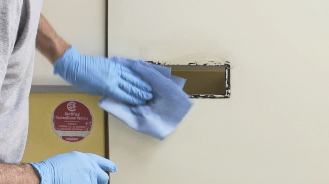
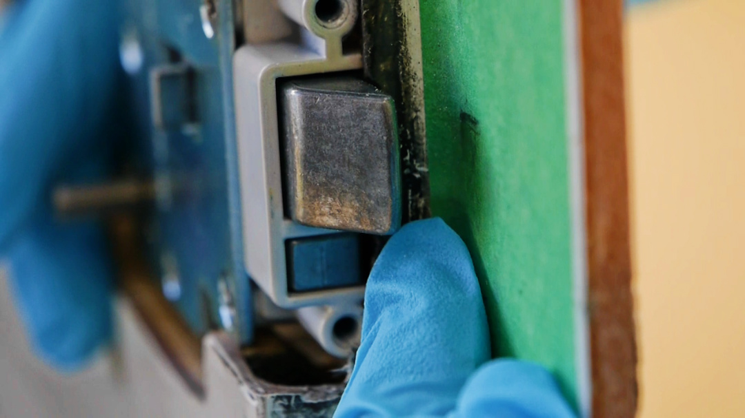
- With the original lock removed, thoroughly clean the area ensuring that all sealant has been removed.
- It is best to use a petroleum free solvent that does not leave any residue, these include:
- Methyl Hydrate or Methyl Alcohol
- Acetone
- Mineral Spirits
- Brake Cleaner
NOTE: read and follow product precautions for the solvent being used
NOTE: wear protective gloves when handling chemicals
NOTE: many solvents are flammable, use with caution, dispose of rags in a safe manner
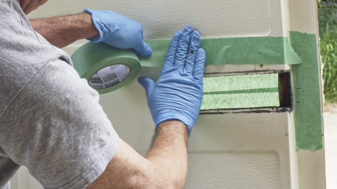
Apply masking tape to the inside and outside of the door to protect the fibreglass surfaces and for marking the cut lines where the new lock set will be installed
Marking the Opening
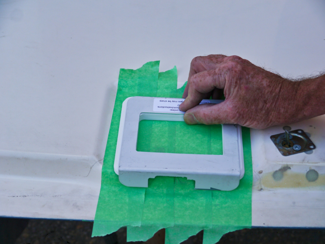
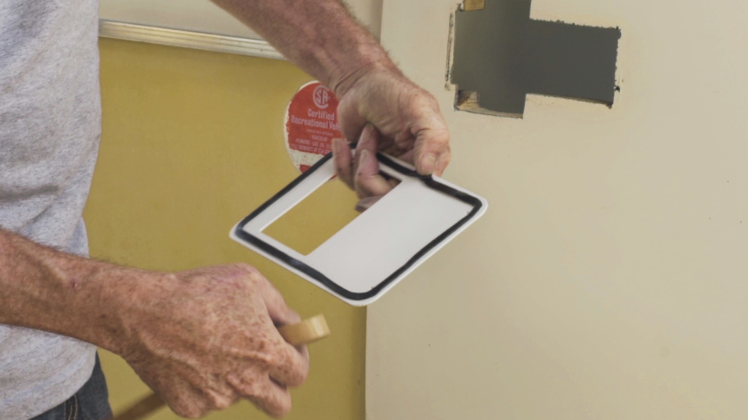
- Position the Inner aluminum adapter plate (part #2) along with the Latch Cover (part #4) and the Spacers (part #5, #6) that were identified in the “Measure the Door” step.
- Hold these tight against the surface of the door with the bent edge against the edge of the door. DO NOT bend or force the aluminum plate to match the angled door edge, just position it so the edge of the aluminum plate touches the edge of the door.
- If there is a recessed area moulded into the surface of the door, centre the adapter plate in the recessed area.
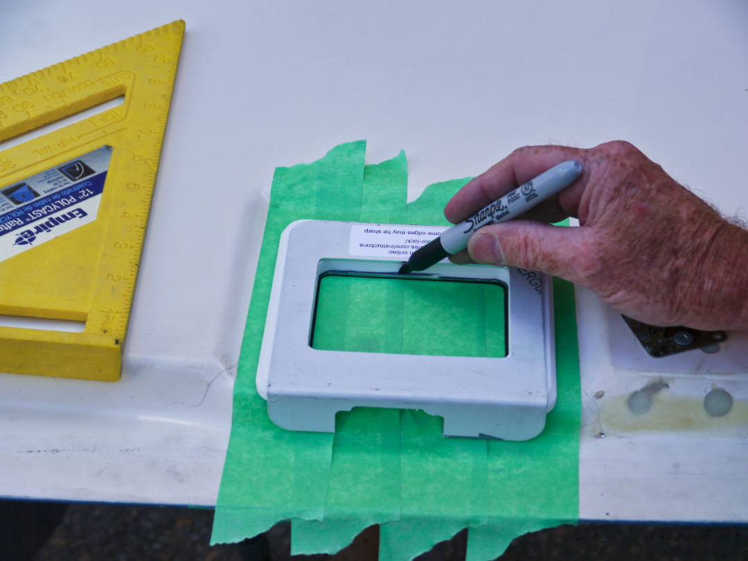
- With a marker or pencil draw the around the rectangular area inside of the adapter plate
NOTE: This will be the cut-out for the new lock set
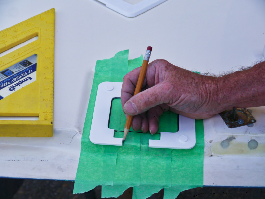
- Holding the “C” shaped spacer plate (part #5) over the lines you just drew, with a pencil or marker also mark around the opening towards the outer door edge.
- Make sure you hold the spacer so the opening is aligned with the notch in the aluminum plate for the latch bolts
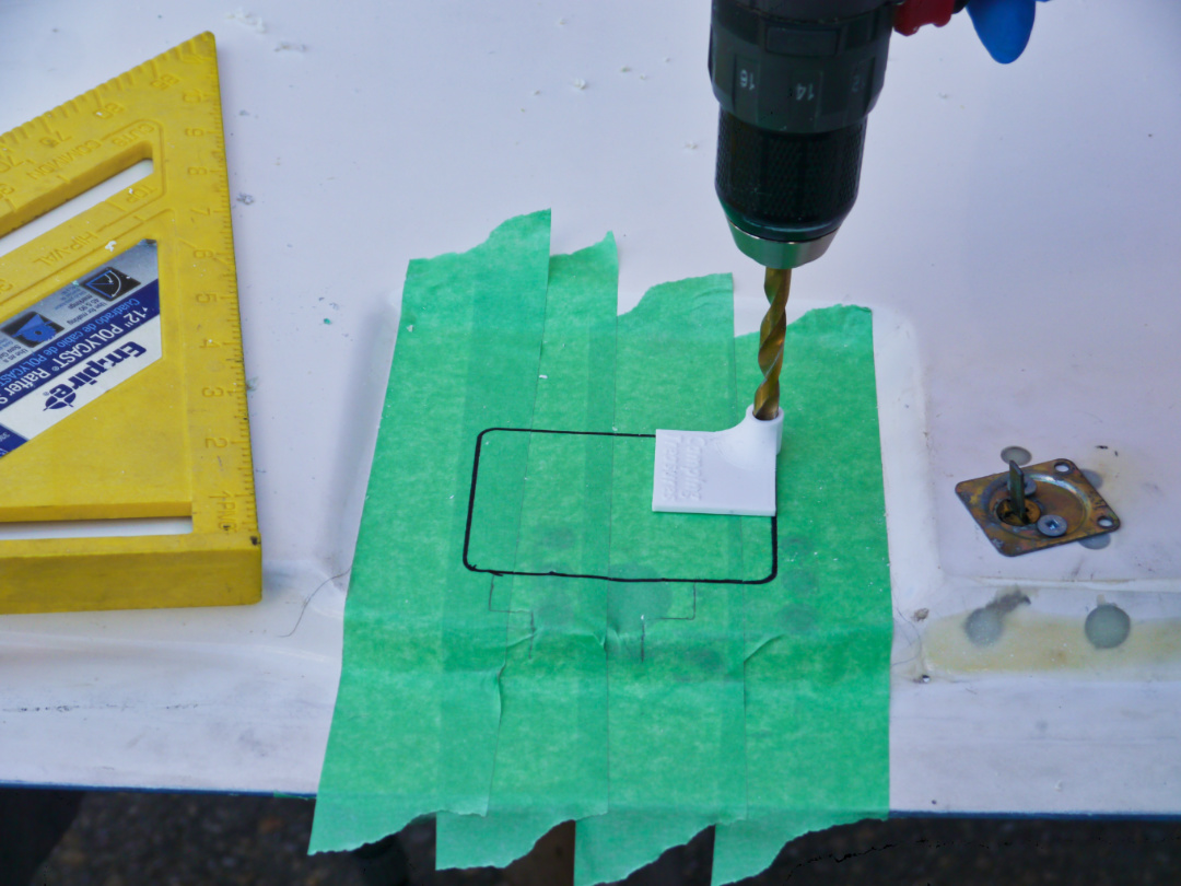
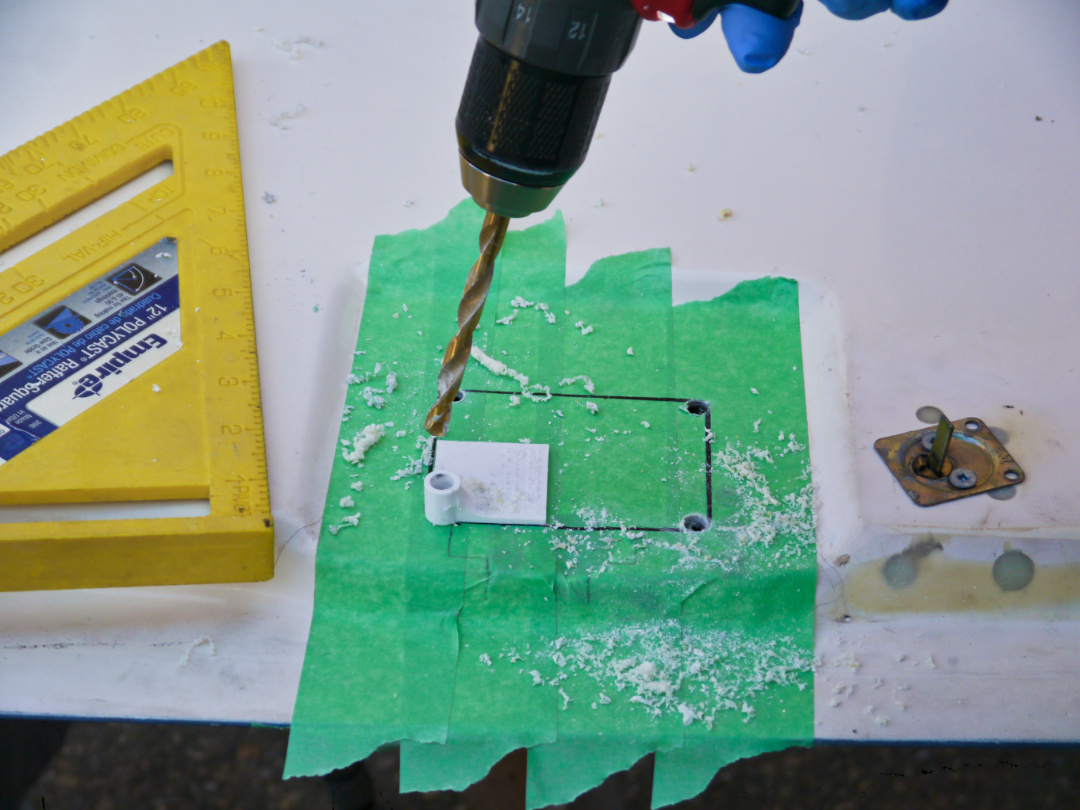
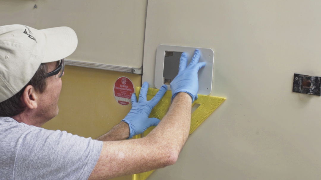
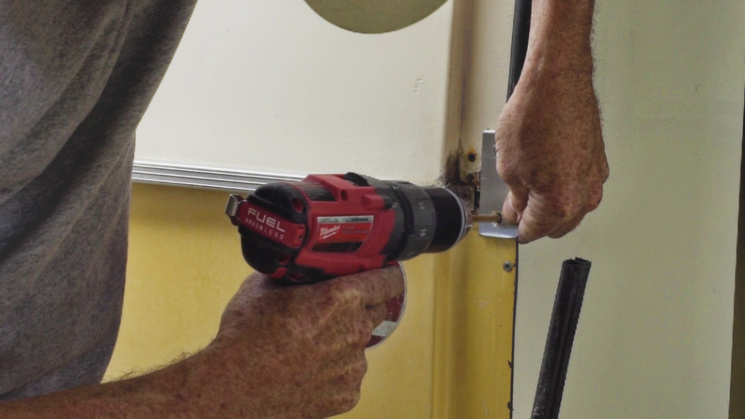
- Using a 5/16” drill bit and the included corner dill guide (part #16), drill holes through the door at the corners, make sure you drill these holes at 90 degrees to the door surface
- These holes locate the new opening on the outside of the door.
The drill jig (part #16) included is designed to make the holes as straight as possible, in the corners and 90 deg to the door surface
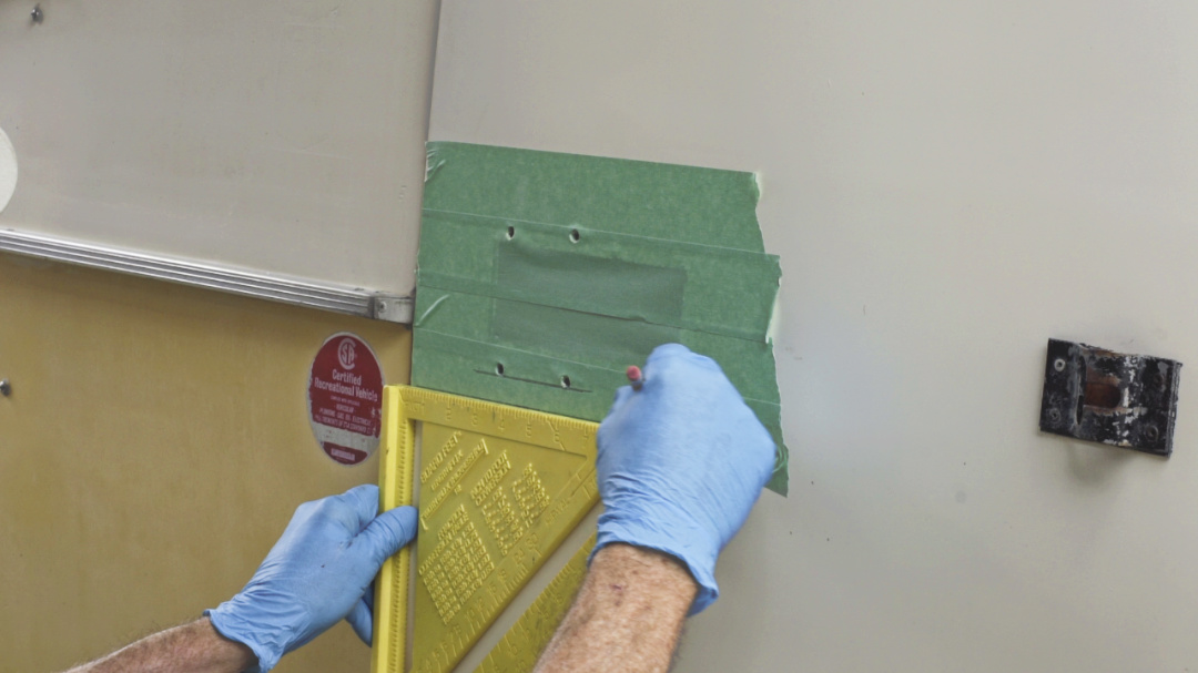
- Use a T-square along the edge of the door, draw a line along the bottom of the lower two holes you just drilled.
- Align and square the Outer aluminum adapter plate (part #3) with this line and trace around the inside opening to mark the lockset cutout. This mark on the outside of the door is the area the new door lock will be mounted.
- Again use the T square against the edge of the door to make sure the outer plate is square
NOTE: if the corner marking holes don’t line up perfectly don’t worry, these will be covered by the plate
Cutting the Opening
PLEASE NOTE:
- Fibreglass dust can be very irritating to your skin and eyes and is very hazardous to breath.
- Protect yourself, wear long sleeve clothing, the disposable gloves (part #18) and dust mask (part #19) included in the kit, and eye protection
NOTE: There are two separate cutting steps, one step you cut through both the inner and outer door panels the door to mount the lock, the second step you cut ONLY the inside panel for the latch bolt
- The best jigsaw blade for cutting fibreglass is one that is designed for cutting ceramic tile (a grit blade) but a fine tooth blade designed for cutting metal also works well on fibreglass.
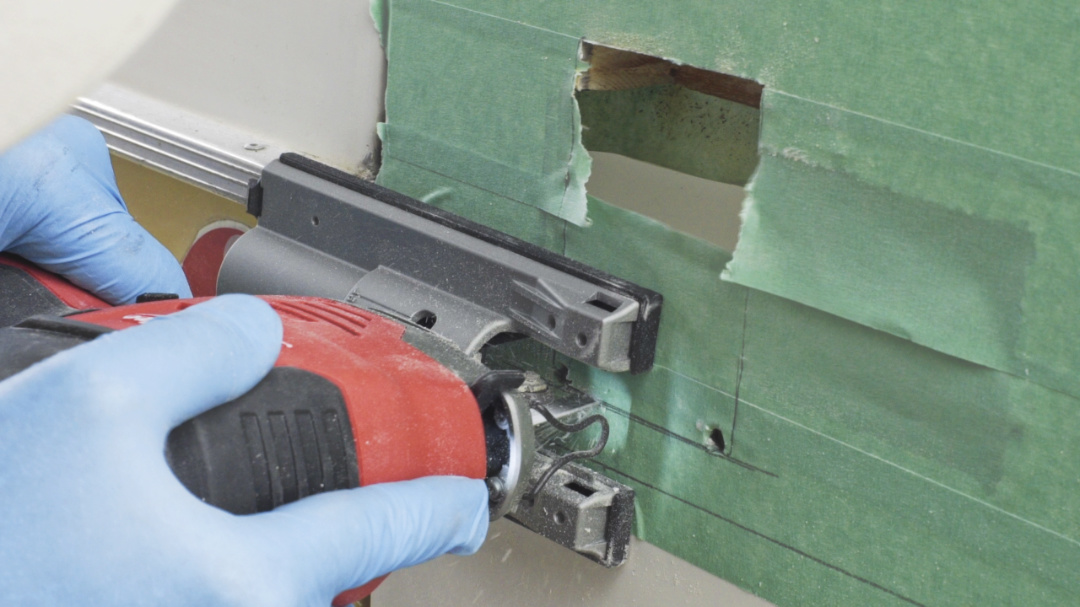
- Cut the rectangular opening for the door handle, from the outside of the door use a jigsaw on a slow speed, cut out the rectangle along the lines you marked. This is the only area where you cut completely through the door
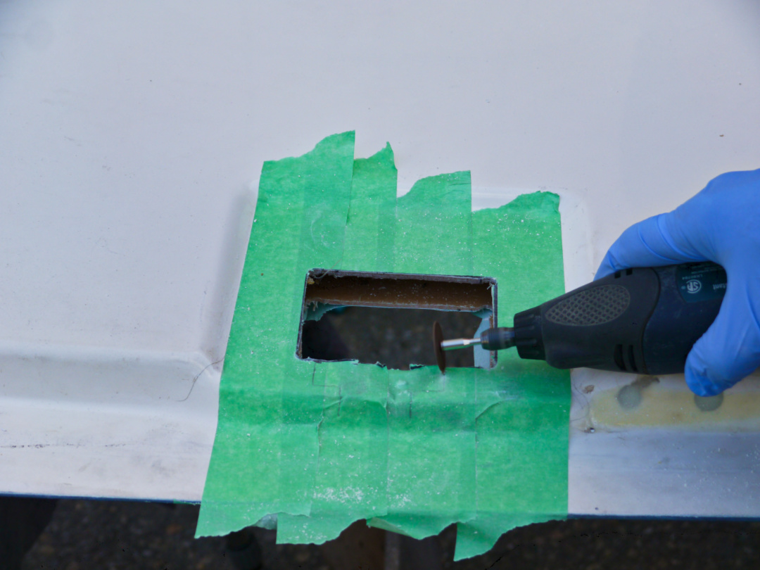
- Next, using a small cut-off wheel on a Dremel or similar tool cut along the lines on the inside of the door for the latch bolt, cut ONLY through the inner door surface, do not cut through the outer skin of the door. Remove any inner door filler in the cutout area.
- Place the door lock into the cut opening to test the fit, trim any fibreglass that may interfere with the lock.

Drilling Holes to Secure Latch Cover and Spacers
- Hold the ¼” Latch Cover (part #4) over the opening you cut through the door, align and level the cover with both the opening you cut and with the edge of the door, drill a 3/16” hole through the inner door panel.
- Holding the latch cover (part #4), measure the door thickness, this measurement has to be 1 ⅜” to 1 ½”.
- Using the two plastic spacers supplied with the kit (parts #5 & #6), install the spacers as needed between the inner door surface and the plastic latch cover (part #4) to attain a total door thickness of 1 ⅜” to 1 ½”.
NOTE: boler doors vary considerably in thickness, the supplied ⅛” and ¼” thick spacers (parts #5 & #6) are used separately or together, along with the latch cover (part #4), this allows you to adjust the door thickness to fit exactly
- Align the latch cover (part #4) and spacers (parts #5 & #6) that are needed, insert the two large head rivets (part #15) through them and into the holes drilled in the door.
- With a rivet gun set the rivet firmly, making sure that the top of the rivet does not protrude above the surface of the latch cover.
- Place the Outer aluminum adapter plate (part #3) on the outside surface of the door. Use masking tape on two edges to temporarily hold the plate in position
- Test fit the new lock assembly (part #1) and adjust the opening as needed, being careful not to make the opening too large.
- Some trimming or fitting of the fibreglass on the edge of the door may be needed around the latch bolt.
- Make sure that the two small tabs on the latch housing do not bind, the latch must fit tight on the outside surface of the door. Use a file if needed to adjust the opening in the door.
- Check along the edge of the door to make sure the latch bolts move freely and doesn’t bind or hit anything, again some trimming or filing of the fibreglass may be needed around the latch bolt.
- If you removed the door you can re-install the door at any time. Follow the instructions making sure you do not over-tighten the bolt and spring. https://www.campingtreasures.com/instructions/rebuilding-boler-scamp-hinges/
Installing the Lock Assembly
- Remove the protective film from both sides of the outer aluminum adapter plate (part #3).
- Apply the butyl tape (part #17) to the back side of the outer adapter plate, try to keep the butyl tape ¼” to ½” away from the edge of the adapter plate.
- Stretch the butyl tape as you apply it, this will make it thinner, all you need is a continuous bead of the butyl tape around the perimeter thick enough to seal, if applied too thick the excess will be squeezed out along the edge and can prevent the plate from sitting flat against the door.
- Remove the masking tape on the door and clean the surface with rubbing alcohol.
- Press the outside plate firmly into position making sure the cutout aligns and the plate is square to the edge of the door.
- Attach the Outer aluminum adapter plate (part #3) by drilling through the four 1/8″ holes in the plate and into the outer surface of the door
- Install the four aluminum pop rivets (part #14) into the plate and door
- Remove the protective film from the both sides of the inner aluminum adapter plate (part #2).
- Apply several short strips of butyl tape (part #17) to the back side of the inner aluminum adapter plate (part #2)) to hold it in place, install the
Install the door lock assembly (part #1) into the door, loosely tighten the two #8-32 flat head machine screws (part #8) into the latch bolt end of the lockset

- Install the inside door lock handle and assembly, ensure to align the inside latch and install 4 screws (part #9), do not tighten yet.
NOTE: 2 sets of #8-32 machine screws are included with the kit to connect the inner latch handle plate to the the latch assembly (¾” long and 1″ long), if the ¾” long screws are not long enough to engage the screws then use the 1”
- When tightening the 4 screws (parts #9) make sure the plastic arm on the inside plate fully engages the latch release lever on the door lock assembly. Gradually tighten the 4 screws in a criss-cross pattern until snug, do not over tighten.
- After the screws are tight, test the inside handle several times to make sure the latch works freely.
NOTE: On thicker doors it is possible that if the inside latch arm is not fully engaged it can flip over the release lever making it impossible for the door to be opened from the inside without removing the inside assembly and manually pulling the release lever.

- Tighten the two flat head machine screws (part #8) above and below the latch bolts.
- Double check the door latch and deadbolt operates freely from both the inside and outside handles.
Installing the Striker Plate
The reason aluminum is used for the striker plate rather than steel is because over time the aluminum will wear rather than the steel in the latch bolt. The aluminum striker plate is very easy and inexpensive to replace when compared to replacing the door latch assembly.
- Close the door to see if the original striker plate will latch
- In most cases the latch will not engage the original striker plate and the supplied aluminum striker plate will need to be installed
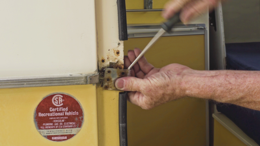
- If the latch bolts do not engage the original striker plate then remove the plate by drilling out the two pop rivets then use a screwdriver or small pry bar to remove the latch plate
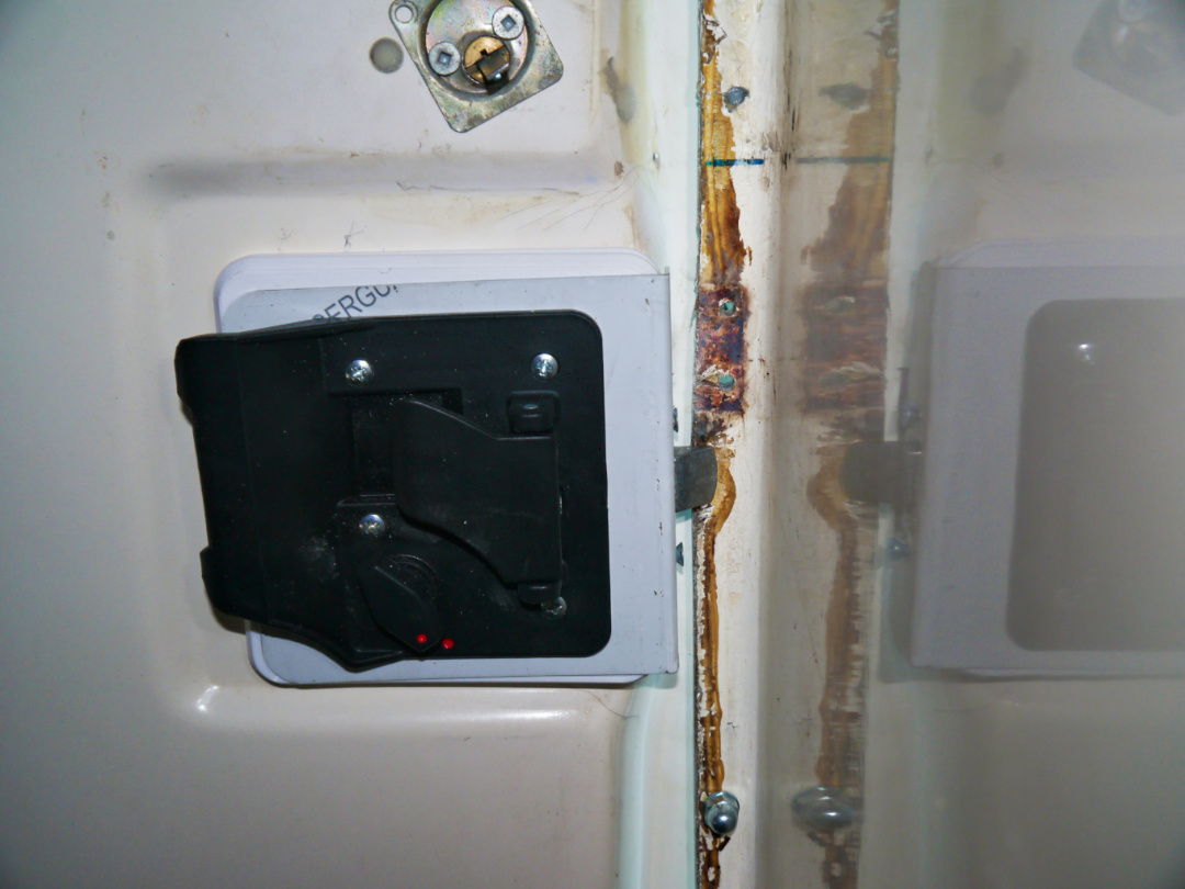
- In most cases the fibreglass door jam needs to be trimmed slightly to allow the latch bolt and deadbolt to full extend.
NOTE: In this picture the fibreglass on the door jam interferes with the end of the door latch and the dead bolt and will need to be trimmed to allow the latch bolt to fully extend behind the striker plate.
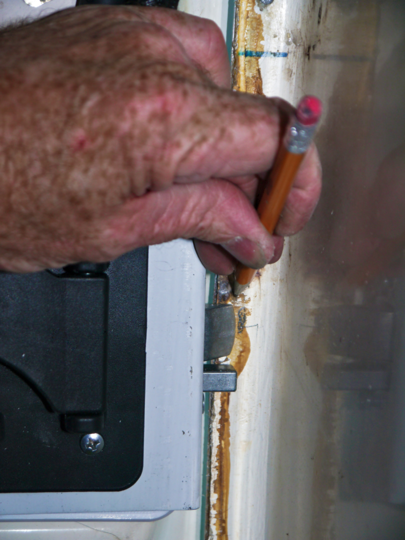
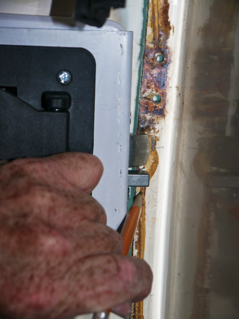
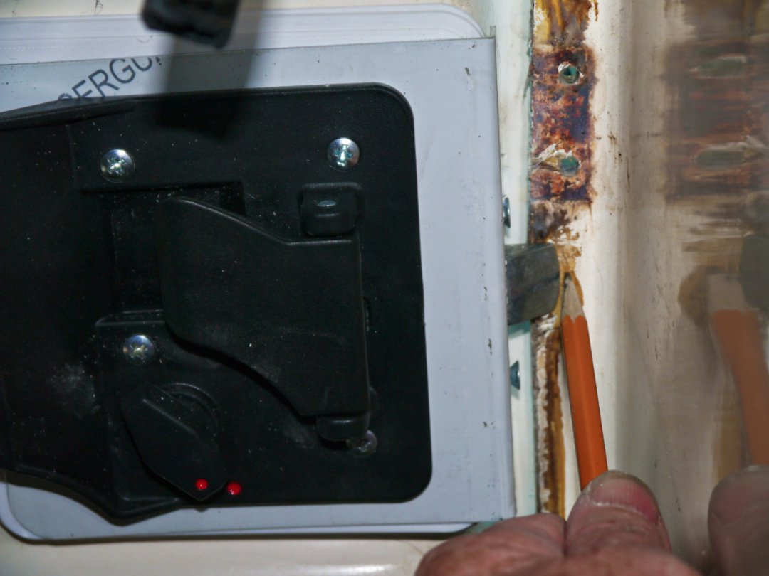
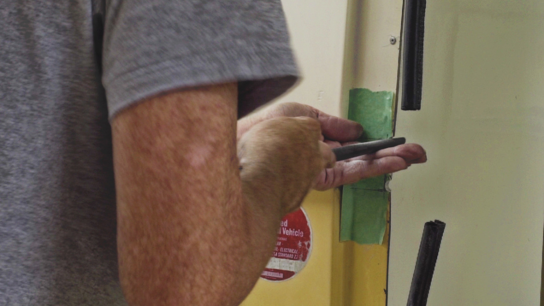
- Mark the jam about 1/8″ above, below and past the extended the latch and deadbolt
- This shows how much the edge of the door jam needs to be trimmed
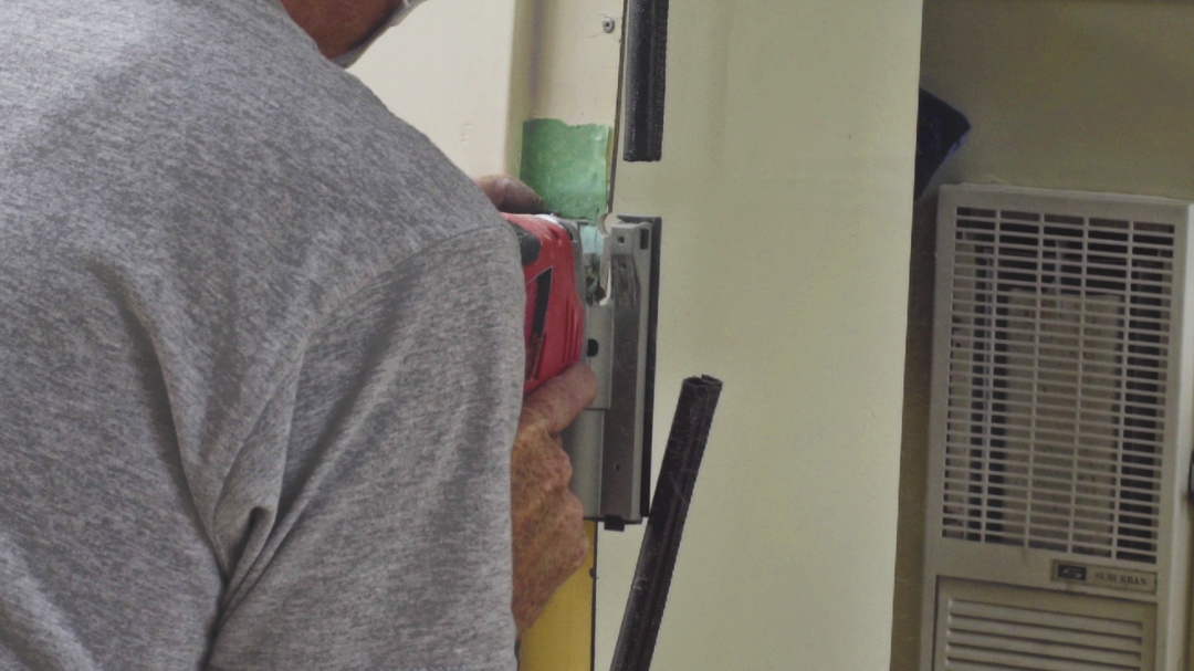
- Use a round file on the top and bottom mark then the jig saw to cut the remaining fibreglass. Usually the door jam only has to be trimmed about ¼”
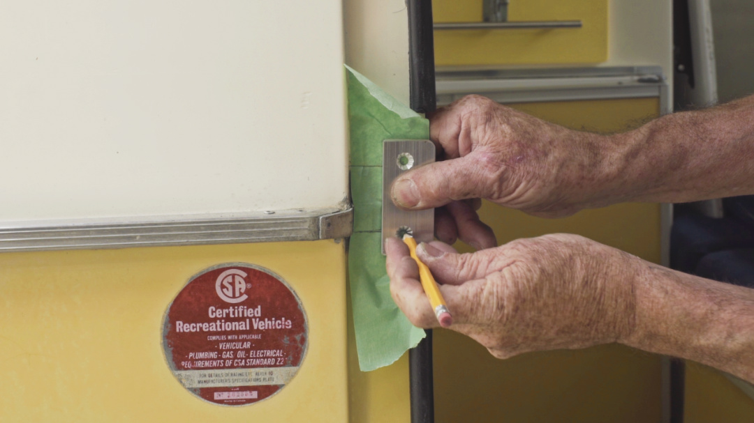
- The flat aluminum striker plate (part #7) is installed on the outside of the door jam by centering it with the latch bolts, use the marks you made on the masking tape as a reference
- With the door closed measure the distance from the edge of the door jam to the side of the door, position the striker plate so it does not hit the door but the latch bolt if fully engaged (usually the striker plate sits about ¼” proud of the edge of the jam
- Drill two – 3/16” holes through the fibreglass, Start by drilling one hole then install the flat head machine screw (part #11) through the striker plate and door jam, then install a washer (part #12) and nut (part #13) on the back side and snug it up. Then align the plate, drill the second holes, install the machine screw, washer and nut and tighten both machine screws.
- Test close the door, and adjust as needed
- Remove any excess butyl tape that has squeezed out then clean the area with a cloth or shop rag dampened in solvent
CONGRATULATIONS!
Your new lock assembly is complete
Installing the Camping Treasures Door Lock Kit in a 1975 to 1988 boler
The following video is for newer 1975 to 1988 boler but the door lock installation is very similar.
I recommend you watch this video to help understand the steps to install the door lock.
I am working on a new video on installing the 1968 to 1974 Door Lock Kit, I will post it on this page as soon as it is available